Sunday, March 20, 2016
arduino RF-Receiver Code
/*
Example for receiving
http://code.google.com/p/rc-switch/
If you want to visualize a telegram copy the raw data and
paste it into http://test.sui.li/oszi/
*/
#include
RCSwitch mySwitch = RCSwitch();
int a=0;
int relay = 5;
void setup() {
Serial.begin(9600);
mySwitch.enableReceive(0); // Receiver on inerrupt 0 => that is pin #2
}
void loop() {
if (mySwitch.available()) {
a = mySwitch.getReceivedValue();
if(a == 17715){
//Serial.println("Relay ON");
digitalWrite(ledPin, HIGH);
}
if(a == 17724){
//Serial.println("Relay OFF");
digitalWrite(ledPin, LOW);
}
mySwitch.resetAvailable();
}
}
Tuesday, September 22, 2015
ESP8266 Remote Controlled Sockets | ESP8266 control 433mhz remote control
i get this tutorial on website http://randomnerdtutorials.com/esp8266-remote-controlled-sockets/ , i copy from this site for my own purpose documentation, please refer to that website for detail
Parts List
Here’s the hardware that you need to complete this project:
RC Switch Library Download
Here’s the Arduino library you need for this project:
- Download the RC Switch library
- Unzip the RC Switch library
- Remove the “-” from the folder name, otherwise your Arduino IDE won’t recognize your library
- Install the RC Switch library in your Arduino IDE
- Restart your Arduino IDE
The RC Switch library is great and it works with almost all remote controlled sockets in the market.
Receiver Circuit
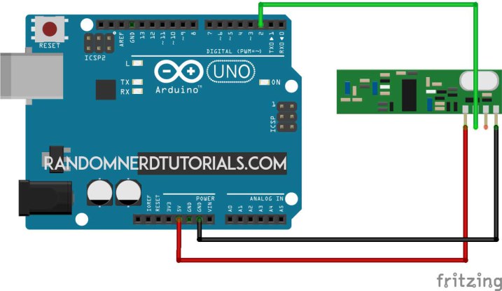
Follow the circuit above for your receiver. Then upload the code below or you can go to File > Examples > RC Switch > ReceiveDemo_Advanced.
/*********
Rui Santos
Complete project details at http://randomnerdtutorials.com
*********/
#include <RCSwitch.h>
RCSwitch mySwitch = RCSwitch();
void setup() {
Serial.begin(9600);
mySwitch.enableReceive(0); // Receiver on inerrupt 0 => that is pin #2
}
void loop() {
if (mySwitch.available()) {
output(mySwitch.getReceivedValue(), mySwitch.getReceivedBitlength(), mySwitch.getReceivedDelay(), mySwitch.getReceivedRawdata(),mySwitch.getReceivedProtocol());
mySwitch.resetAvailable();
}
}
Save the TriState Values
Open your Arduino serial monitor at a baud rate of 9600 and start pressing the buttons of your remote. Save the TriState values (highlighted in red) of each key in a notepad.

Schematics (3.3V FTDI Programmer)
The schematics to upload code to your ESP8266 are very straight forward. You only need to establish a serial communication between your FTDI programmer and your ESP8266 to upload some code.

Uploading your ESP8266 code
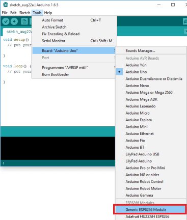
Having the ESP8266 add-on for the Arduino IDE installed (How to Install the ESP8266 Board in Arduino IDE). Go to Tools and select “Generic ESP8266 Module”.
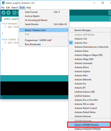
Copy the sketch below to your Arduino IDE. Replace the SSID and password with your own credentials. You also need to change the TriState values. After modifying my sketch upload it to your ESP8266.
/*********
Rui Santos
Complete project details at http://randomnerdtutorials.com
*********/
#include <ESP8266WiFi.h>
#include <WiFiClient.h>
#include <ESP8266WebServer.h>
#include <ESP8266mDNS.h>
#include <RCSwitch.h>
RCSwitch mySwitch = RCSwitch();
MDNSResponder mdns;
// Replace with your network credentials
const char* ssid = "YOUR_SSID";
const char* password = "YOUR_PASSWORD";
ESP8266WebServer server(80);
// Replace with your remote TriState values
char* socket1TriStateOn = "0FFF0FFFFFFF";
char* socket1TriStateOff = "0FFF0FFFFFF0";
char* socket2TriStateOn = "0FFFFF0FFFFF";
char* socket2TriStateOff = "0FFFFF0FFFF0";
String webPage = "";
void setup(void){
webPage += "<h1>ESP8266 Web Server</h1><p>Socket #1 <a href=\"socket1On\"><button>ON</button></a> <a href=\"socket1Off\"><button>OFF</button></a></p>";
webPage += "<p>Socket #2 <a href=\"socket2On\"><button>ON</button></a> <a href=\"socket2Off\"><button>OFF</button></a></p>";
mySwitch.enableTransmit(2);
delay(1000);
Serial.begin(115200);
WiFi.begin(ssid, password);
Serial.println("");
// Wait for connection
while (WiFi.status() != WL_CONNECTED) {
delay(500);
Serial.print(".");
}
Serial.println("");
Serial.print("Connected to ");
Serial.println(ssid);
Serial.print("IP address: ");
Serial.println(WiFi.localIP());
if (mdns.begin("esp8266", WiFi.localIP())) {
Serial.println("MDNS responder started");
}
server.on("/", [](){
server.send(200, "text/html", webPage);
});
server.on("/socket1On", [](){
server.send(200, "text/html", webPage);
mySwitch.sendTriState(socket1TriStateOn);
delay(1000);
});
server.on("/socket1Off", [](){
server.send(200, "text/html", webPage);
mySwitch.sendTriState(socket1TriStateOff);
delay(1000);
});
server.on("/socket2On", [](){
server.send(200, "text/html", webPage);
mySwitch.sendTriState(socket2TriStateOn);
delay(1000);
});
server.on("/socket2Off", [](){
server.send(200, "text/html", webPage);
mySwitch.sendTriState(socket2TriStateOff);
delay(1000);
});
server.begin();
Serial.println("HTTP server started");
}
void loop(void){
server.handleClient();
}
ESP8266 IP Address
Open the Arduino serial monitor at a baud rate of 115200. Connect GPIO 0 of your ESP8266 to VCC and reset your board.
After a few seconds your IP address should appear. In my case it’s 192.168.1.70.

Final Circuit
This is the final circuit for your ESP8266 that hosts a web server and transmits RF signals to control your sockets.

Demonstration
For the final demonstration open any browser from a device that is connected to the same router that your ESP is. Then type the IP address and click Enter!




Now when you press the buttons in your web server you can control both sockets (watch the video at the beginning of this project for a live demo).

Wednesday, September 2, 2015
RTC with dosing pump
// Deven Rich 12-5-2013
// This project was built on the Arduino Uno - ATmega328P
// I would also like to give credit to Maurice Ribble for providing chunks of the RTC code
// This code sets up the DS1307 Real Time clock on the Arduino board to controll 3 dosing pumps
// The RTC keeps track of time, the code checks it and turns on the pumps at a specified time
// to dose your aquarium
#include "Wire.h"
#define DS1307_I2C_ADDRESS 0x68
// Convert normal decimal numbers to binary coded decimal
byte decToBcd(byte val)
{
return ( (val/10*16) + (val%10) );
}
// Convert binary coded decimal to normal decimal numbers
byte bcdToDec(byte val)
{
return ( (val/16*10) + (val%16) );
}
// Stops the DS1307, but it has the side effect of setting seconds to 0
// Probably only want to use this for testing
/*void stopDs1307()
{
Wire.beginTransmission(DS1307_I2C_ADDRESS);
Wire.write(0);
Wire.writeWire.writeWire.write(0x80);
Wire.endTransmission();
}*/
// 1) Sets the date and time on the ds1307
// 2) Starts the clock
// 3) Sets hour mode to 24 hour clock
// Assumes you're passing in valid numbers
void setDateDs1307(byte second, // 0-59
byte minute, // 0-59
byte hour, // 1-23
byte dayOfWeek, // 1-7
byte dayOfMonth, // 1-28/29/30/31
byte month, // 1-12
byte year) // 0-99
{
Wire.beginTransmission(DS1307_I2C_ADDRESS);
Wire.write(0);
Wire.write(decToBcd(second)); // 0 to bit 7 starts the clock
Wire.write(decToBcd(minute));
Wire.write(decToBcd(hour)); // If you want 12 hour am/pm you need to set
// bit 6 (also need to change readDateDs1307)
Wire.write(decToBcd(dayOfWeek));
Wire.write(decToBcd(dayOfMonth));
Wire.write(decToBcd(month));
Wire.write(decToBcd(year));
Wire.endTransmission();
}
// Gets the date and time from the ds1307
void getDateDs1307(byte *second,
byte *minute,
byte *hour,
byte *dayOfWeek,
byte *dayOfMonth,
byte *month,
byte *year)
{
// Reset the register pointer
Wire.beginTransmission(DS1307_I2C_ADDRESS);
Wire.write(0);
Wire.endTransmission();
Wire.requestFrom(DS1307_I2C_ADDRESS, 7);
// A few of these need masks because certain bits are control bits
*second = bcdToDec(Wire.read() & 0x7f);
*minute = bcdToDec(Wire.read());
*hour = bcdToDec(Wire.read() & 0x3f); // Need to change this if 12 hour am/pm
*dayOfWeek = bcdToDec(Wire.read());
*dayOfMonth = bcdToDec(Wire.read());
*month = bcdToDec(Wire.read());
*year = bcdToDec(Wire.read());
}
//define pins
int motorPin1 = 9;
int motorPin2 = 10;
int motorPin3 = 11;
void setup() // run once, when the sketch starts
{
byte second, minute, hour, dayOfWeek, dayOfMonth, month, year;
pinMode(motorPin1, OUTPUT);
pinMode(motorPin2, OUTPUT);
pinMode(motorPin3, OUTPUT);
Wire.begin();
Serial.begin(9600);
// Change these values to what you want to set your clock to.
// You only need to run this the first time you setup your RTC.
// Set the correct value below and un comment it to run it.
/*
second = 45;
minute = 55;
hour = 9;
dayOfWeek = 2;
dayOfMonth = 30;
month = 4;
year = 13;
setDateDs1307(second, minute, hour, dayOfWeek, dayOfMonth, month, year);
*/
}
void loop() // run over and over again
{
byte second, minute, hour, dayOfWeek, dayOfMonth, month, year;
// this prints the output to the serial window (tools > serial monitor in arduino) and is great for testing
getDateDs1307(&second, &minute, &hour, &dayOfWeek, &dayOfMonth, &month, &year);
Serial.print(hour, DEC);
Serial.print(":");
Serial.print(minute, DEC);
Serial.print(":");
Serial.print(second, DEC);
// Set the time you want the motors to kick in
if((hour == 21)&&(minute == 23)&&(second==10)){
Serial.print(" TRUE");
Serial.println(" ");
Serial.println(" MP1");
analogWrite(motorPin1, 255);
delay(8500); // set how long you want the motor to run... 1000 = aprox 1ml
analogWrite(motorPin1, 0);
Serial.println(" MP2");
analogWrite(motorPin2, 255);
delay(9500); // set how long you want the motor to run... 1000 = aprox 1ml
analogWrite(motorPin2, 0);
Serial.println(" MP3");
analogWrite(motorPin3, 255);
delay(5500); // set how long you want the motor to run... 1000 = aprox 1ml
analogWrite(motorPin3, 0);
}
// we dont really need this since we set the pin to low above but just incase <img src="http://fishtankprojects.com/wp-includes/images/smilies/simple-smile.png" alt=":)" class="wp-smiley" style="height: 1em; max-height: 1em;">
else{Serial.println(" false");
analogWrite(motorPin1, 0);
analogWrite(motorPin2, 0);
analogWrite(motorPin3, 0);
}
delay(1000);
}
// This project was built on the Arduino Uno - ATmega328P
// I would also like to give credit to Maurice Ribble for providing chunks of the RTC code
// This code sets up the DS1307 Real Time clock on the Arduino board to controll 3 dosing pumps
// The RTC keeps track of time, the code checks it and turns on the pumps at a specified time
// to dose your aquarium
#include "Wire.h"
#define DS1307_I2C_ADDRESS 0x68
// Convert normal decimal numbers to binary coded decimal
byte decToBcd(byte val)
{
return ( (val/10*16) + (val%10) );
}
// Convert binary coded decimal to normal decimal numbers
byte bcdToDec(byte val)
{
return ( (val/16*10) + (val%16) );
}
// Stops the DS1307, but it has the side effect of setting seconds to 0
// Probably only want to use this for testing
/*void stopDs1307()
{
Wire.beginTransmission(DS1307_I2C_ADDRESS);
Wire.write(0);
Wire.writeWire.writeWire.write(0x80);
Wire.endTransmission();
}*/
// 1) Sets the date and time on the ds1307
// 2) Starts the clock
// 3) Sets hour mode to 24 hour clock
// Assumes you're passing in valid numbers
void setDateDs1307(byte second, // 0-59
byte minute, // 0-59
byte hour, // 1-23
byte dayOfWeek, // 1-7
byte dayOfMonth, // 1-28/29/30/31
byte month, // 1-12
byte year) // 0-99
{
Wire.beginTransmission(DS1307_I2C_ADDRESS);
Wire.write(0);
Wire.write(decToBcd(second)); // 0 to bit 7 starts the clock
Wire.write(decToBcd(minute));
Wire.write(decToBcd(hour)); // If you want 12 hour am/pm you need to set
// bit 6 (also need to change readDateDs1307)
Wire.write(decToBcd(dayOfWeek));
Wire.write(decToBcd(dayOfMonth));
Wire.write(decToBcd(month));
Wire.write(decToBcd(year));
Wire.endTransmission();
}
// Gets the date and time from the ds1307
void getDateDs1307(byte *second,
byte *minute,
byte *hour,
byte *dayOfWeek,
byte *dayOfMonth,
byte *month,
byte *year)
{
// Reset the register pointer
Wire.beginTransmission(DS1307_I2C_ADDRESS);
Wire.write(0);
Wire.endTransmission();
Wire.requestFrom(DS1307_I2C_ADDRESS, 7);
// A few of these need masks because certain bits are control bits
*second = bcdToDec(Wire.read() & 0x7f);
*minute = bcdToDec(Wire.read());
*hour = bcdToDec(Wire.read() & 0x3f); // Need to change this if 12 hour am/pm
*dayOfWeek = bcdToDec(Wire.read());
*dayOfMonth = bcdToDec(Wire.read());
*month = bcdToDec(Wire.read());
*year = bcdToDec(Wire.read());
}
//define pins
int motorPin1 = 9;
int motorPin2 = 10;
int motorPin3 = 11;
void setup() // run once, when the sketch starts
{
byte second, minute, hour, dayOfWeek, dayOfMonth, month, year;
pinMode(motorPin1, OUTPUT);
pinMode(motorPin2, OUTPUT);
pinMode(motorPin3, OUTPUT);
Wire.begin();
Serial.begin(9600);
// Change these values to what you want to set your clock to.
// You only need to run this the first time you setup your RTC.
// Set the correct value below and un comment it to run it.
/*
second = 45;
minute = 55;
hour = 9;
dayOfWeek = 2;
dayOfMonth = 30;
month = 4;
year = 13;
setDateDs1307(second, minute, hour, dayOfWeek, dayOfMonth, month, year);
*/
}
void loop() // run over and over again
{
byte second, minute, hour, dayOfWeek, dayOfMonth, month, year;
// this prints the output to the serial window (tools > serial monitor in arduino) and is great for testing
getDateDs1307(&second, &minute, &hour, &dayOfWeek, &dayOfMonth, &month, &year);
Serial.print(hour, DEC);
Serial.print(":");
Serial.print(minute, DEC);
Serial.print(":");
Serial.print(second, DEC);
// Set the time you want the motors to kick in
if((hour == 21)&&(minute == 23)&&(second==10)){
Serial.print(" TRUE");
Serial.println(" ");
Serial.println(" MP1");
analogWrite(motorPin1, 255);
delay(8500); // set how long you want the motor to run... 1000 = aprox 1ml
analogWrite(motorPin1, 0);
Serial.println(" MP2");
analogWrite(motorPin2, 255);
delay(9500); // set how long you want the motor to run... 1000 = aprox 1ml
analogWrite(motorPin2, 0);
Serial.println(" MP3");
analogWrite(motorPin3, 255);
delay(5500); // set how long you want the motor to run... 1000 = aprox 1ml
analogWrite(motorPin3, 0);
}
// we dont really need this since we set the pin to low above but just incase <img src="http://fishtankprojects.com/wp-includes/images/smilies/simple-smile.png" alt=":)" class="wp-smiley" style="height: 1em; max-height: 1em;">
else{Serial.println(" false");
analogWrite(motorPin1, 0);
analogWrite(motorPin2, 0);
analogWrite(motorPin3, 0);
}
delay(1000);
}
Tuesday, August 25, 2015
internal pull-up resistor
#define BUTTON_PIN 2

void setup()
{
  ...
  pinMode(BUTTON_PIN, INPUT);
  digitalWrite(BUTTON_PIN, HIGH); // connect internal pull-up
  ...
}

void loop()
{
  ...
}
arduino RF transmitter / receiver
download VirtualWire.h
https://www.pjrc.com/teensy/td_libs_VirtualWire.html
// RX code
// Include VirtualWire library
#include <VirtualWire.h>
// Pins definition
const int led_pin = 13;
const int receive_pin = 12;
int pinSpeaker = 10;
void setup()
{
Serial.begin(9600); // Debugging only
// Initialise the IO and ISR
vw_set_rx_pin(receive_pin);
vw_setup(4000); // Transmission rate
// Start the receiver PLL
vw_rx_start();
// Set LED pin and Buzzer
pinMode(led_pin, OUTPUT);
pinMode(pinSpeaker, OUTPUT);
}
void loop()
{
uint8_t buf[VW_MAX_MESSAGE_LEN];
uint8_t buflen = VW_MAX_MESSAGE_LEN;
// Check if a message was received
if (vw_get_message(buf, &buflen))
{
if(buf[0]=='1')
{
Serial.println("Motion detected!");
digitalWrite(led_pin,1);
playTone(300, 160);
delay(150);
}
if(buf[0]=='0')
{
Serial.println("Motion ended!");
digitalWrite(led_pin,0);
playTone(0, 0);
delay(300);
}
}
}
// duration in mSecs, frequency in hertz
void playTone(long duration, int freq)
{
duration *= 1000;
int period = (1.0 / freq) * 1000000;
long elapsed_time = 0;
while (elapsed_time < duration)
{
digitalWrite(pinSpeaker,HIGH);
delayMicroseconds(period / 2);
digitalWrite(pinSpeaker, LOW);
delayMicroseconds(period / 2);
elapsed_time += (period);
}
}
VirtualWire is an Arduino library that provides features to send short messages, without addressing, retransmit or acknowledgment, a bit like UDP over wireless, using ASK (amplitude shift keying). Supports a number of inexpensive radio transmitters and receivers.
This library allow You to send and receive data"byte" and string easily ,
First Download the library from Here .
after extract the folder, and move it to " Libraries " on the arduino Folder
this is a simple code , it will send character '1' and after 2 sec will send character '0' and so on .
this code for transmitter :
==========================================================

https://www.pjrc.com/teensy/td_libs_VirtualWire.html
// RX code
// Include VirtualWire library
#include <VirtualWire.h>
// Pins definition
const int led_pin = 13;
const int receive_pin = 12;
int pinSpeaker = 10;
void setup()
{
Serial.begin(9600); // Debugging only
// Initialise the IO and ISR
vw_set_rx_pin(receive_pin);
vw_setup(4000); // Transmission rate
// Start the receiver PLL
vw_rx_start();
// Set LED pin and Buzzer
pinMode(led_pin, OUTPUT);
pinMode(pinSpeaker, OUTPUT);
}
void loop()
{
uint8_t buf[VW_MAX_MESSAGE_LEN];
uint8_t buflen = VW_MAX_MESSAGE_LEN;
// Check if a message was received
if (vw_get_message(buf, &buflen))
{
if(buf[0]=='1')
{
Serial.println("Motion detected!");
digitalWrite(led_pin,1);
playTone(300, 160);
delay(150);
}
if(buf[0]=='0')
{
Serial.println("Motion ended!");
digitalWrite(led_pin,0);
playTone(0, 0);
delay(300);
}
}
}
// duration in mSecs, frequency in hertz
void playTone(long duration, int freq)
{
duration *= 1000;
int period = (1.0 / freq) * 1000000;
long elapsed_time = 0;
while (elapsed_time < duration)
{
digitalWrite(pinSpeaker,HIGH);
delayMicroseconds(period / 2);
digitalWrite(pinSpeaker, LOW);
delayMicroseconds(period / 2);
elapsed_time += (period);
}
}
===========================================
// TX code
// Include VirtualWire library
#include <VirtualWire.h>
int led_pin = 13;
int transmit_pin = 12;
int pir_pin = 2;
int val = 0;
int pir_state = LOW;
void setup()
{
Serial.begin(9600);
vw_set_tx_pin(transmit_pin);
vw_setup(4000); // Transmission rate
pinMode(led_pin, OUTPUT);
pinMode(pir_pin,INPUT);
}
void loop()
{
char msg[1] = {'0'};
// Get sensor value
val = digitalRead(pir_pin);
// Change message if motion is detected
if (val == 1)
{
msg[0] = '1';
digitalWrite(led_pin, HIGH); // Flash a light to show transmitting
vw_send((uint8_t *)msg, 1);
vw_wait_tx(); // Wait until the whole message is gone
if (pir_state == LOW)
{
Serial.println("Motion detected!");
pir_state = HIGH;
}
}
else
{
msg[0] = '0';
digitalWrite(led_pin, LOW);
vw_send((uint8_t *)msg, 1);
vw_wait_tx(); // Wait until the whole message is gone
if (pir_state == HIGH)
{
Serial.println("Motion ended!");
pir_state = LOW;
}
}
}
===================================
another code :
VirtualWire is an Arduino library that provides features to send short messages, without addressing, retransmit or acknowledgment, a bit like UDP over wireless, using ASK (amplitude shift keying). Supports a number of inexpensive radio transmitters and receivers.
This library allow You to send and receive data"byte" and string easily ,
First Download the library from Here .
after extract the folder, and move it to " Libraries " on the arduino Folder
this is a simple code , it will send character '1' and after 2 sec will send character '0' and so on .
this code for transmitter :
//simple Tx on pin D12
//Written By : Mohannad Rawashdeh
// 3:00pm , 13/6/2013
//http://www.genotronex.com/
//..................................
#include <VirtualWire.h>
char *controller;
void setup() {
pinMode(13,OUTPUT);
vw_set_ptt_inverted(true); //
vw_set_tx_pin(12);
vw_setup(4000);// speed of data transfer Kbps
}
void loop(){
controller="1" ;
vw_send((uint8_t *)controller, strlen(controller));
vw_wait_tx(); // Wait until the whole message is gone
digitalWrite(13,1);
delay(2000);
controller="0" ;
vw_send((uint8_t *)controller, strlen(controller));
vw_wait_tx(); // Wait until the whole message is gone
digitalWrite(13,0);
delay(2000);
}
and this is code for receiver :
The D13 LED On the arduino board must be turned ON when received character '1' and Turned Off when received character '0'
The D13 LED On the arduino board must be turned ON when received character '1' and Turned Off when received character '0'
//simple Tx on pin D12
//Written By : Mohannad Rawashdeh
// 3:00pm , 13/6/2013
//http://www.genotronex.com/
//..................................
#include <VirtualWire.h>
void setup()
{
vw_set_ptt_inverted(true); // Required for DR3100
vw_set_rx_pin(12);
vw_setup(4000); // Bits per sec
pinMode(13, OUTPUT);
vw_rx_start(); // Start the receiver PLL running
}
void loop()
{
uint8_t buf[VW_MAX_MESSAGE_LEN];
uint8_t buflen = VW_MAX_MESSAGE_LEN;
if (vw_get_message(buf, &buflen)) // Non-blocking
{
if(buf[0]=='1'){
digitalWrite(13,1);
}
if(buf[0]=='0'){
digitalWrite(13,0);
}
}
}
==========================================================
how to calculate length of antenna

The way to calculate the antenna length is to divide the speed of light by the frequency to calculate the wavelength, and divide that by 4 to get a quarter length.
In my case the frequency is 433Mhz
Speed of the light is 3x10^8 m/s
Wavelength = Speed of light (c) / Frequency (f)
= ( 3x10^8) / (433x10^6)
= 0.69284 m
Antenna length = Wavelength /4
=0.69284/4 = 0.1732 m =17.32 cm or 6.82 inch
From the above calculation it comes out to about 17.3 cm or 6.8 inches. Just cut a piece of wire 6.8 inches long and solder it into that hole marked with ANT, on each module. putting the wires on there makes a great difference.
Subscribe to:
Posts (Atom)